|
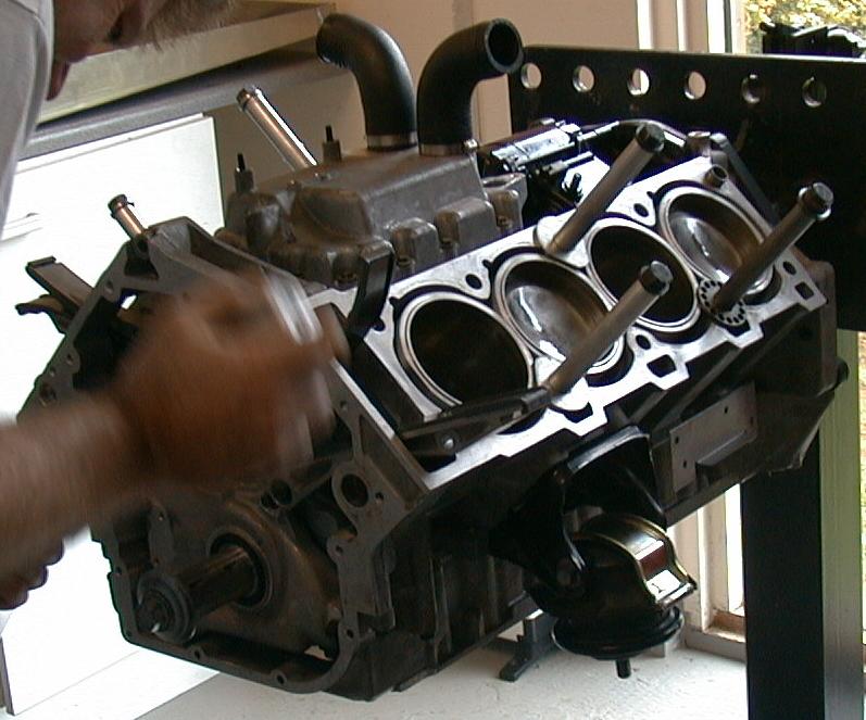
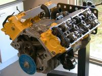
This is the bare short block after a small amount of work. Daniel has put in
all the pistons and attached them to the crankshaft. Geoff is seen here
bolting on the chain tensioners. The large washers used to hold in the
cylinder sleeves are visible, and are still necessary at this point as the
sleeves are loose-fit in the block. They will eventually be held in place
by the heads.
|

|
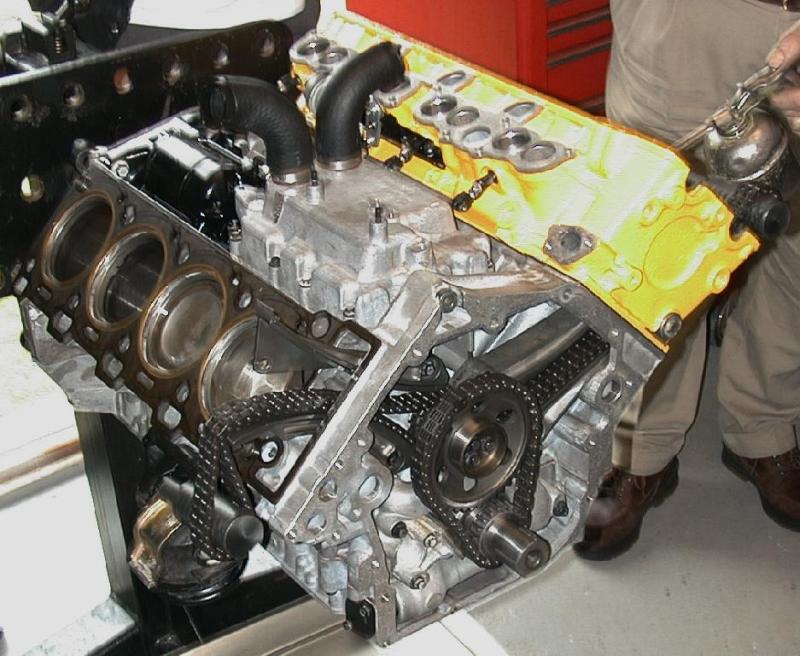
Geoff has installed the cam chains and is in the process of putting the heads
on.
Valve actuators are being oiled and installed
in preparation for the cams being installed.
|

|
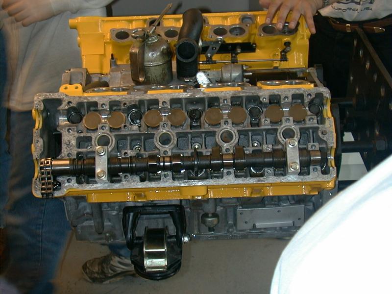
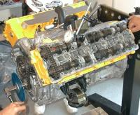
Here we see the cams being installed. The two pieces that are used to pull the
cams down are not the actual cam caps. The caps are meant only to hold the
cams in place during while the cam covers are put on, they are not designed
to take much stress at all, as it is the cam covers that actually hold the
cams in the journals. The shiny circles along the top cam journal are the
valve actuators that were being installed in the previous frame. At the moment
here they are being installed in the far head.
|
|
Both heads are on and 'factory' cam timing has been set. Note the T-shaped
tools that are placed in the
cams. These were/are used to quickly set the cam timing by turning the crank
to top dead center on cylinder 1 and then turning the cams until the pins slide
into holes that are machined into the cams.
This allows the cams to be set to the factory timing of 114o to
within about a degree.
Note that even though the caps
are on the block pieces used to pull the cams down are still on for
reinforcement. Geoff is very careful to always set these pieces so as not
to over stress the caps.
A degree wheel has been attached to the crank to allow the timing to be changed
from the factory value.
|
|
The pin of this dial indicator is resting on the valve plate, notice the
curved portion of the measurement shaft that goes around the cam. This is
used to find maximum open position (MOP) for this valve.
By comparing top dead
center on the cylinder (to which the degree wheel was set previously) and MOP on
this valve, the timing can be set for this cam. The process is then repeated
for the exhaust cam. We set these cams both to 110o for a
performance boost. These are still the factory cams, just at different
timings. Note again that the pieces used to pull the cams into place are
still being used for support, one on each cam.
|

|
Now we move on to setting the timing on the other side, this time on
cylinder 6, since top dead center is still the same. These two cams
go much more quickly than the first set, I guess we're getting the hang of
this thing. The cam cover has been put on the completed cams, and each bolt
torqued down. After the other cams are finished, it will be time to pull
out the tensioning bolts and put in the actual cam chain tensioners.
|

|
|
|
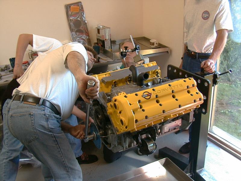
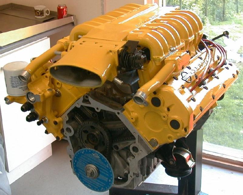
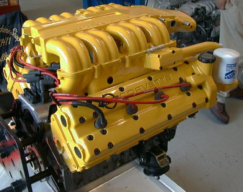
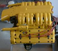
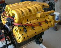
A thing of beauty (If you like bananas). The cams are now set up and the
covers on. The rest of the yellow pieces have been put on to give a nice
picture. (If you look closely there are no bolts holding the plenum on.)
The wires will be black in the end and the lettering will be filled in with
black paint. A pretty good day's work I'd say.
|